Bluetooth Low Energy (BLE)
Table of Contents
- 1. 蓝牙简介
- 2. BLE 协议栈
- 3. BLE Physical Layer
- 4. BLE Link Layer
- 5. Host Controller Interface (HCI)
- 6. Logical Link Control and Adaptation Protocol (L2CAP)
- 7. Security Manager (SM)
- 8. Generic Access Profile (GAP)
- 9. Attribute Protocol (ATT)
- 10. Generic Attribute Profile (GATT)
- 11. Android, iOS
- 12. Tips
- 13. 参考
1. 蓝牙简介
蓝牙(Bluetooth)是一种近距离无线连接技术,它最初由爱立信公司开发。
1.1. 蓝牙标准
蓝牙大版本号的发布时间如表 1 所示。
| Version | 发布时间 | 主要新功能 | 说明 |
|---|---|---|---|
| 1.0 | 1998 | ||
| 2.0 | 2004 | Enhanced Data Rate (EDR) | |
| 3.0 | 2009 | AMP (Alternative MAC/PHY) 技术,即利用 802.11 实现高速(High Speed)蓝牙 | 蓝牙 1.0 到 3.0 都被称为“经典蓝牙” |
| 4.0 | 2010 | Bluetooth Low Energy (BLE) | BLE 技术曾经也使用术语 Bluetooth Smart |
| 5.0 | 2016 | 无重大新功能,针对物联网优化。比如,BLE 的调制速率最高可支持 2 Mbit/s (之前为 1 Mbit/s) |
1.2. 蓝牙系统框架
蓝牙系统框架如图 1 所示(摘自 BLUETOOTH CORE SPECIFICATION Version 5.3 | Vol 1, Part A)。
Figure 1: Bluetooth Core System Architecture
从图 1 中可知, 蓝牙的系统结构可以分为 Controller 层和 Host 层, 这两层之间是 HCI(Host Controller Interface)。
低功耗蓝牙(LE)和经典蓝牙(BR/EDR)相差很大,可以认为是两套独立系统,它们之间是不互通的。 这两套系统在图 1 中分别对应两个不同的 Controller,不过,蓝牙系统并不需要都集成这两个 Controller,图 2(摘自 BLUETOOTH CORE SPECIFICATION Version 5.3 | Vol 1, Part A)描述的是 Host 和 Controller 常见的搭配组合。
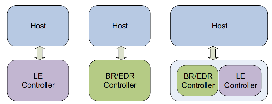
Figure 2: Bluetooth Host and Controller combinations: (from left to right): LE Only Controller, BR/EDR only Controller, and BR/EDR/LE Controller
1.3. 蓝牙 Profile
Profile 是蓝牙对应于每一个具体的应用场景的无线接口规范。Bluetooth 的一个很重要特性,就是 Bluetooth 产品无须实现全部的 Bluetooth 规范。蓝牙设备可以选择支持某一些 Profile。 比如用于文件传输的 File Transfer Profile,用于音频输出的 Advenced Audio Distribution Profile,还有一些常用的蓝牙 Profile 可参考:https://en.wikipedia.org/wiki/List_of_Bluetooth_profiles
2. BLE 协议栈
BLE 是 Bluetooth Low Energy 的缩写,在蓝牙 4.0 中引入,是“功耗极低”的短距离无线通信技术。BLE 体系结构(或者说协议栈)分为三个基本部分,如图 3 所示(摘自“Getting Started with Bluetooth Low Energy”,其实只是在图 1 基础下摘取了 BLE 相关部分,并加入了 Application 层)。
Figure 3: The BLE protocol stack
低功耗蓝牙的体系结构分成三个基本部分:控制器(Controller)、主机(Host)和应用程序(Application):
- 控制器通常是一个“物理设备”,它能够发送和接收无线电信号,并懂得如何将这些信号翻译成携带信息的数据包。
- 主机通常是一个“软件栈”,管理两台或多台设备间如何通信以及如何利用无线电同时提供几种不同的服务。
- 应用程序,是上层应用,它使用下层的软件栈。
从图 3 中可知,应用程序打交道的是主要是 Generic Access Profile(GAP)和 Generic Attribute Profile(GATT)。
3. BLE Physical Layer
BLE 物理层主要规定了下面事项:
- BLE 是无线通信,它所使用的频段为 ISM 频段,其频率范围是 2.400-2.4835 GHz;为了同时支持多个设备,整个频带分为 40 份,每份的带宽为 2 MHz,称作 RF Channel。 在任意某个时刻,BLE 只会使用其中某一个 RF Channel。
- 发射端的相关特性,比如发射功率(Transmission Power)、调制方式(Modulation)等等。
- 接收端的相关特性,比如接收灵敏度等等。
注 1:ISM 频段(Industrial Scientific Medical Band)主要是开放给工业、科学和医用 3 个主要机构使用的频段,这个频段属于无需许可的频段,很多设备都工作在这个频段内,如 Wi-Fi。
注 2:经典蓝牙的频率范围也是 2.400-2.4835 GHz,不过经典蓝牙把这个频带分为了 79 份,每份的带宽为 1 MHz,如表 2 所示。
| Regulatory Range | RF Channels | |
|---|---|---|
| 经典蓝牙 | 2.400-2.4835 GHz | f=2402+k MHz, k=0,…,78 |
| BLE | 2.400-2.4835 GHz | f=2402+k*2 MHz, k=0,…,39 |
3.1. 调制
调制(Modulation)就是对信号源的信息进行处理加到载波上,使其变为适合于信道传输的形式的过程。按调制信号的形式可分为模拟调制和数字调制,BLE 采用了数字调制。常用的数字调制信号主要包括幅度键控(ASK)、频移键控(FSK)、相移键控(PSK)和正交幅度调制(QAM)信号。BLE 采用了频移键控(FSK),也就是通过改变载波的频率,来表征比特信息:如果调制波的频率高于载波频率,则表示比特 1,如果低于,则表示比特 0。
BLE 5.0 中定义两种调制方式:1 Msym/s 调制和 2 Msym/s 调制。
在 1 Msym/s 调制方式支持两种 PHY:
(1) LE 1M PHY,信息数据不编码,传输速率为 1 Mb/s。
(2) LE Coded PHY,信息数据编码方式,传输速率为 125 kb/s 或者 500 kb/s。
在 2 Msym/s 调制方式下支持单一 PHY:
(1) LE 2M PHY,信息数据不编码,传输速率就为 2 Mb/s。
所以,一共有 3 种物理层,如表 3 所示。
| 物理层 | 调制速率 | 编码方案(报头部分) | 编码方案(载荷部分) | 比特率 | 说明 |
|---|---|---|---|---|---|
| LE 1M PHY | 1 Msym/s | 无 | 无 | 1 Mb/s | Bluetooth 4.0 中就有 |
| LE 2M PHY | 2 Msym/s | 无 | 无 | 2 Mb/s | Bluetooth 5.0 中新增,BLE 设备能“更快地”传输信号 |
| LE Coded PHY | 1 Msym/s | 编码 S=8 | 编码 S=8 或者 S=2 | 125kb/s 或者 500 kb/s | Bluetooth 5.0 中新增,引入 了 FEC 编解码以及 Pattern Mapper 和 Demapper 部分, 以降低传输速率,增加接收机复杂度为代价,使得 BLE 设备能“更远地”传输信号,从而更好地适应物联网应用 |
4. BLE Link Layer
链路层的主要功能有:
- 多个通信实体的 RF Channel 共享问题。BLE 物理层定义了 40 个 RF Channel,任意某时刻,只会使用其中某一个。BLE 中参与通信的实体的数量,不止这个数量级。链路层需要解决 RF Channel 的共享问题;
- 构建两个通信实体的逻辑链路(Logical Link)。对这两个实体来说,如果它们看到的是一条自己独享的传输通道,这就是所谓的逻辑链路。
- 数据传输可能损毁、丢失,需要提供校验、重传等机制,确保数据传输的可靠性。
4.1. 两类通道
- 0-36 信道是 General Purpose Channel(Data Channel)。
- 37/38/39 信道是 Primary Advertising Channel,它的主要作用是 Discovering Devices, Initiating a Connection, and Broadcasting Data。
注:Primary Advertising Channel(即 BLE 的 37/38/39 信道)的选择特意避开了 Wi-Fi 常用的 1/16/11 通道,如图 4(摘自:https://www.accton.com/Technology-Brief/ble-beacons-and-location-based-services/ )所示。
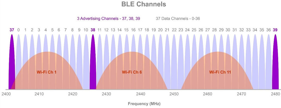
Figure 4: BLE 两类通道,其中 Primary Advertising Channel 避开了 Wi-Fi 常用的 1/6/11 通道
两个 BLE 设备建立连接(即处于 Connection 状态,后文会介绍)后,在同一时刻只会使用一个物理信道。BLE 使用 Hopping 算法(参考节 4.1.1)来决定使用哪个信道。
信道总数才 40 个,当空间内有大量的设备时,很可能会出现信道冲突。如何缓解这个问题呢?解决办法是每个链路层的数据包中都有一个“Access Address”字段,“Access Address”是信道的一个标识。每建立一次连接时,会重新生成一次 Access Addres。
4.1.1. 跳频算法(Hopping)
蓝牙工作在繁忙的 ISM 频段(有很多无线设备工作在这个频段,如常见的 Wi-Fi), 为了提高系统的抗干扰能力,连接建立后不会长期使用一个固定的 Physical Channel,而是在多个信道之间随机但有规律地切换,这就是蓝牙的 Hopping 算法。
BLE 中定义了两个跳频算法:Channel Selection Algorithm #1(这个算法是 Bluetooth 4.0 中引入的)和 Channel Selection Algorithm #2(这个算法是 Bluetooth 5.0 中引入的)。
下面仅介绍第 1 个跳频算法,它的跳频公式如下:
unmappedChannel = (lastUnmappedChannel + hopIncrement) mod 37
fn+1=(fn+hop) mod 37, hop 是一个 5-16 的随机值,在每次链路建立之后固定。协议规定第一次连接事件中 fn=0,fn+1=(0+hop) mod 37。
算法的流程如图 5 所示。
Figure 5: Channel Selection Algorithm #1
4.1.2. 跳频算法实例
下面介绍 Channel Selection Algorithm #1 的一个例子。
假设主机 ChanelMap = 00011110 00000000 11100000 00000110 00000000b,最右边为第 0 信道,最左边为第 39 信道。
那么使用到的信道为 9, 10, 21, 22, 23, 33, 34, 35, 36。
usedChannel[] = {9,10,21,22,23,33,34,35,36}, 即 numUsedChannel(N) = 9
Last Unmapped Channel 的初值值为 0(之后为每次计算出来的 unmappedChannel);
假设 hopIncrement = 7, 则
unmappedChannel = (0+7)mod37 = 7,而 7 信道不是一个可用的信道,那么就要重映射,N=9
remappingIndex = 7mod N = 7
又 usedChannel[7] = 35
所以 data channel index = 35。
4.2. 状态机及其 7 种状态
链路层的操作可以使用状态机来描述,在链路层抽象出了 7 种状态:
- Standby State
- Advertising State
- Scanning State
- Initiating State
- Connection State
- Synchronization State(注:这是 Bluetooth 5.1 中新加入的)
- Isochronous Broadcasting State(注:这是 Bluetooth 5.2 中新加入的)
在状态机中,同一时刻只有一个状态被激活。链路层至少有一个状态机实例,链路层可以有多个状态机实例。
状态机的状态转移如图 6 所示。
Figure 6: State diagram of the Link Layer state machine
下面是前 5 个状态的说明:
- Standby 状态是初始状态,即不发送数据,也不接收数据。根据上层实体的命令(如位于 Host 软件中 GAP),可由其它任何一种状态进入,也可以切换到除 Connection 状态外的任意一种状态。
- Advertising 状态是可以通过广播通道发送数据的状态,由 Standby 状态进入。它广播的数据可以由处于 Scanning 或者 Initiating 状态的实体接收。上层实体可通过命令将 Advertising 状态切换回 Standby 状态。另外,连接成功后,也可切换为 Connection 状态。
- Scanning 状态是可以通过广播通道接收数据的状态,由 Standby 状态进入。根据 Advertiser 所广播的数据的类型,有些 Scanner 还可以主动向 Advertiser 请求一些额外数据。上层实体可通过命令将 Scanning 状态切换回 Standby 状态。
- Initiating 状态和 Scanning 状态类似,不过是一种特殊的接收状态,由 Standby 状态进入,只能接收 Advertiser 广播的 connectable 的数据,并在接收到数据后,发送连接请求,以便和 Advertiser 建立连接。当连接成功后,Initiater 和对应的 Advertiser 都会切换到 Connection 状态。
- Connection 状态是和某个实体建立了单独通道的状态,在通道建立之后,由 Initiating 或者 Advertising 自动切换而来。通道断开后,会重新回到 Standby 状态。
通道建立后(通常说“已连接”),处于 Connection 状态的双方,分别有两种角色 Master 和 Slave。其中, Initiater 方称作 Master,而 Advertiser 方称作 Slave。
参考:http://www.wowotech.net/bluetooth/ble_stack_overview.html
4.3. 链路层数据包的格式(Air Interface Packets)
在 3.1 中介绍了 BLE 有 3 种物理层:LE 1M PHY/LE 2M PHY/LE Coded PHY。
BLE 链路层的数据包有两种格式:
- Packet Format for the LE Uncoded PHYS,这种数据包适应于物理层 LE 1M PHY/LE 2M PHY。
- Packet Format for the LE Coded PHY,这种数据包适应于物理层 LE Coded PHY。
4.3.1. Packet Format for the LE Uncoded PHYS
对于 LE 1M PHY/LE 2M PHY 物理层,介绍的数据包如图 7 所示。
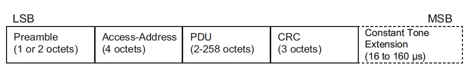
Figure 7: Link Layer packet format for the LE Uncoded PHYs
Preamble(前导帧),对于 LE 1M PHY,根据 Access Address 第一个 Bit,有两种取值:0x55 或者 0xAA(纯 PHY 层行为);对于 LE 2M PHY,根据 Access Address 第一个 Bit,有两种取值:0x5555 或者 0xAAAA(纯 PHY 层行为)。
Access Address,来标示接收者 ID,在节 4.1 有提到过。根据 Access Address 的不同,又区分两种 Packet 类型:广播包和数据包:
- 广播包 Access Address 固定为 0x8E89BED6,广播包只能在广播信道(channel)上传输,即只能在 37/38/39 信道上传输(注:从蓝牙 5.0 开始广播包可以在其它信道上传输)。广播包发送给附近所有的 observer(扫描者)。
- 数据包 Access Address 为一个 32bit 的随机值,由 Initiator 生成。数据包,其实是数据信道上的空中包的简称,数据包只在数据信道上传输,即除 37/38/39 之外的其余 37 信道(BLE 总共占用 40 个信道)。每建立一次连接,重新生成一次 Access Address。数据包是给连接通信使用的,即用于 Master 和 Slave 之间通信的。
PDU(Protocol Data Unit,协议数据单元)。如果是广播包,则 PDU 如图 8 所示;如果是数据包,则 PDU 如图 9 所示。
CRC 占 24-bit,用于对 PDU 进行数据校验。
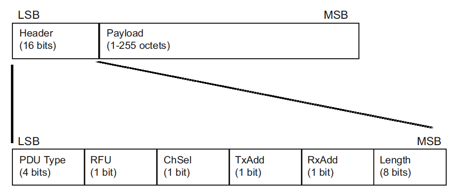
Figure 8: Advertising physical channel PDU
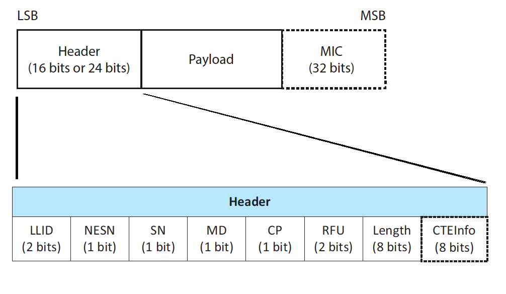
Figure 9: Data Physical Channel PDU
4.3.2. Packet Format for the LE Coded PHY
这里不介绍,有兴趣可以参考 BLUETOOTH CORE SPECIFICATION Version 5.3 | Vol 6, Part B
5. Host Controller Interface (HCI)
HCI 协议连接 Host 和 Controller,将 Host 的操作转化为 HCI 指令传给 Controller,BLE 协议规定了 HCI 的指令集。通常是两颗 IC 之间的通信协议,可基于 Uart、USB 等物理介质。如果 Host 和 Controller 都在同一颗芯片上,则 HCI 不一定必须实现,Host 和 Controller 之间可直接通过自定义的 API 来交互。
6. Logical Link Control and Adaptation Protocol (L2CAP)
经过 Link Layer 的抽象之后,两个 BLE 设备之间可存在两条逻辑上的数据通道:一条是“无连接的广播通道”;另一条是“基于连接的数据通道”,它是一个点对点(Master 和 Slave)的逻辑通道。
广播通道暂且不细说,这个“基于连接的数据通道”(后面简称逻辑通道),要怎么使用,还需要一番思索,例如:逻辑通道只有一条,而要利用它传输数据的上层应用却不止一个(例如图 3 中的 ATT 和 SMP 两个协议都要使用逻辑通道),怎么复用?
Logical Link Control and Adaptation Protocol(L2CAP)提供的最主要功能就是“为上层协议提供复用 Link Layer 逻辑通道的方法”。具体方法是:
数据发送时,将用户数据分割为一定长度的数据包(L2CAP Packet Data Units,PDUs),加上一个包含特定“Channel ID”的header后,通过逻辑链路发送出去。
数据接收时,从逻辑链路接收数据,解析其中的“Channel ID”,并以此判断需要将数据转发给哪个应用。
BLE 中,L2CAP 定义了如图 10 所示的 Channel ID(CID)。这样,0x0004/0x0006 分别表示上层是 ATT/SMP。
Figure 10: Channel ID(CID)的定义
L2CAP 还包含其它一些功能,L2CAP 的功能总结如下:
- Protocol/channel multiplexing,协议/通道的多路复用;
- Segmentation and reassembly,上层应用数据(L2CAP Service Data Units,SDUs)的分割(和重组),生成协议数据单元(L2CAP Packet Data Units,PDUs),以满足用户数据传输对延时的要求,并便于后续的重传、流控等机制的实现;
- Flow control per L2CAP channel,基于 L2CAP Channel 的流控机制;
- Error control and retransmissions,错误控制和重传机制;
- Support for Streaming,支持流式传输(如音频、视频等,不需要重传或者只需要有限重传);
- Fragmentation and Recombination,协议数据单元(PDUs)的分片(和重组),生成符合 Link Layer 传输要求的数据片。
- Quality of Service,QoS 的支持。
参考:http://www.wowotech.net/bluetooth/ble_stack_overview.html
7. Security Manager (SM)
Security Manager (SM) 定义了进行 Pairing 和 Key Distribution 的方法和协议。
Pairing is performed to establish keys which can then be used to encrypt a link. A transport specific key distribution is then performed to share the keys. The keys can be used to encrypt a link in future reconnections, verify signed data, or perform random address resolution.
Pairing 是个 three-phase 协议(其中 Phase 3 是可选的),如图 12(摘自 Bluetooth Specification Version 4.2 [Vol 3, Part H])所示。
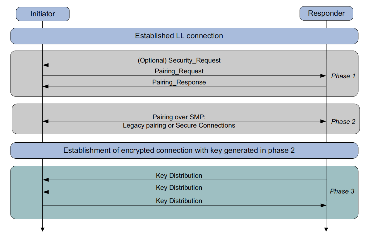
Figure 12: LE Pairing Phases
3 个 Phase 的作用分别如下:
- Phase 1: Pairing Feature Exchange
- Phase 2 (LE legacy pairing): Short Term Key (STK) Generation
- Phase 2 (LE Secure Connections): Long Term Key (LTK) Generation
- Phase 3: Transport Specific Key Distribution
7.1. Phase 1: Pairing Feature Exchange
图 12 中 Pairing_Request/Pairing_Response Packet 格式如 图 13 所示。
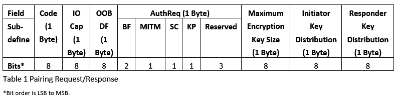
Figure 13: Pairing Request and Pairing Response Packet
第 1 个域 Code 的含义如表 4 所示。
| Code | Description |
|---|---|
| 0x01 | Pairing Request |
| 0x02 | Pairing Response |
第 2 个域 IO Cap 的含义如表 5 所示。
| Value | Description |
|---|---|
| 0x00 | DisplayOnly |
| 0x01 | DisplayYesNo |
| 0x02 | KeyboardOnly |
| 0x03 | NoInputNoOutput |
| 0x04 | KeyboardDisplay |
| 0x05-0xFF | Reserved |
DisplayYesNo 是表示设备可以显示 Yes 和 No 两个按钮供用户交互。
第 3 个域 OOB DF(即 Out-of-Band Data Flag)的含义如表 6 所示。
| Value | Description |
|---|---|
| 0x00 | OOB Authentication data not present |
| 0x01 | OOB Authentication data from remote device present |
| 0x02-0xFF | Reserved |
MITM 是“Man-In-The-Middle”的缩写,这个域占一个 bit,如果为 1 ,则表示设备请求 MITM 保护。SC 是“Secure Connection”的缩写,这个域占一个 bit,如果为 1,则表示设备请求“Secure Connection pairing”。MITM 和 SC 的值会影响到 Phase 2 中到底选择哪一种 Pairing 方式。
7.2. Phase 2: 确定 Pairing 方式
一共有 4 种 Pairing 方式:
- Just Works(明文传输,没有认证保护)
- Passkey(一个设备显示 6 位数字,要求另一个设备输入;如果两个设备都只有键盘,可能是两个设备都输入)
- Out-of-Band
- Numeric Comparison(两个设备都显示 6 位数字,用户确认它们是否相同,这种方式是在 Bluetooth 4.2 中引入的)
有 4 种方式,到底使用哪种方式呢?这是由 Phase 1: Pairing Feature Exchange 传递的 Packet 中的字段来决定的,具体流程如下:
Step 1. 检查 SC 字段是否都为 1;如果都为 1,则进入 Step 2,否则进入 Step 3。
Step 2. 使用图 14 的规则。
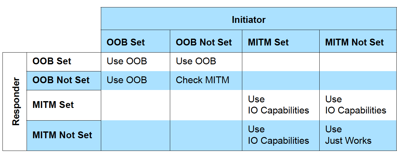
Figure 14: Rules for using Out-of-Band and MITM flags for LE Secure Connections Pairing
图中:
- “Use OOB” means Out-of-Band is selected.
- “Check MITM” means ignore “OOB Data Flag” and check MITM flag, “Man-In-The-Middle” flag.
- “Use IO Capabilities,” go to step 4 to select the key generation method depending on IO Capabilities of both devices.
Step 3. 使用图 15 的规则。
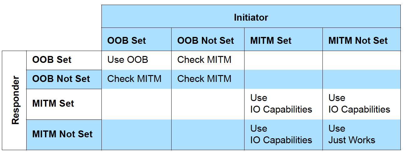
Figure 15: Rules for using Out-of-Band and MITM flags for LE legacy pairing
图中:
- “Use OOB” means Out-of-Band is selected.
- “Check MITM” means ignore “OOB Data Flag” and check the MITM flag, “Man-In-The-Middle” flag.
- “Use IO Capabilities”, go to step 4 to select the key generation method depending on IO Capabilities of both device.
Step 4. 使用图 16 的规则。
Figure 16: Mapping of IO Capabilities to Key Generation Method
参考:
https://www.bluetooth.com/blog/bluetooth-pairing-part-1-pairing-feature-exchange/
https://www.bluetooth.com/blog/bluetooth-pairing-part-2-key-generation-methods/
https://www.bluetooth.com/blog/bluetooth-pairing-passkey-entry/
https://www.bluetooth.com/blog/bluetooth-pairing-part-4/
8. Generic Access Profile (GAP)
The Generic Access Profile (GAP) dictates how devices interact with each other at a lower level, outside of the actual protocol stack. GAP can be considered to define the BLE topmost control layer, given that it specifies how devices perform control procedures such as device discovery, connection, security establishment, and others to ensure interoperability and to allow data exchange to take place between devices from different vendors.
在 BLE 中,GAP 的主要作用:
- Broadcast mode and observation procedure,实现单向的、无连接的通信方式;
- Discovery modes and procedures,实现蓝牙设备的发现操作;
- Connection modes and procedures,实现蓝牙设备的连接操作;
- Bonding modes and procedures,实现蓝牙设备的配对操作;
- Periodic advertising modes and procedure
- Isochronous broadcast modes and procedures
8.1. Roles (Broadcaster/Observer/Central/Peripheral)
GAP 定义了 4 种 Roles:
- Broadcaster(广播员)。适应于周期性地往外发布数据,没有连接状态。表示设备正在发送 Advertising Events。
- Observer(观察者)。适应于周期性地从 Broadcaster 获得数据,没有连接状态。表示设备正在接收 Advertising Events。
- Central(中心设备)。智能手机等 CPU 强大的设备往是 Central,Central 可以连接多个 Peripheral,并从 Peripheral 读取数据。对应于 Link Layer 的 Master Role。
- Peripheral(外围设备)。使用 Advertising Packet,允许 Central 找到它,并连接上它。对应于 Link Layer 的 Slave Role。
图 17(‘M’ 表示 mandatory to support,‘O’ 表示 optional to support,‘E’ for excluded within profile role)定义了 GAP 4 个 Roles 对物理层和链路层的要求。
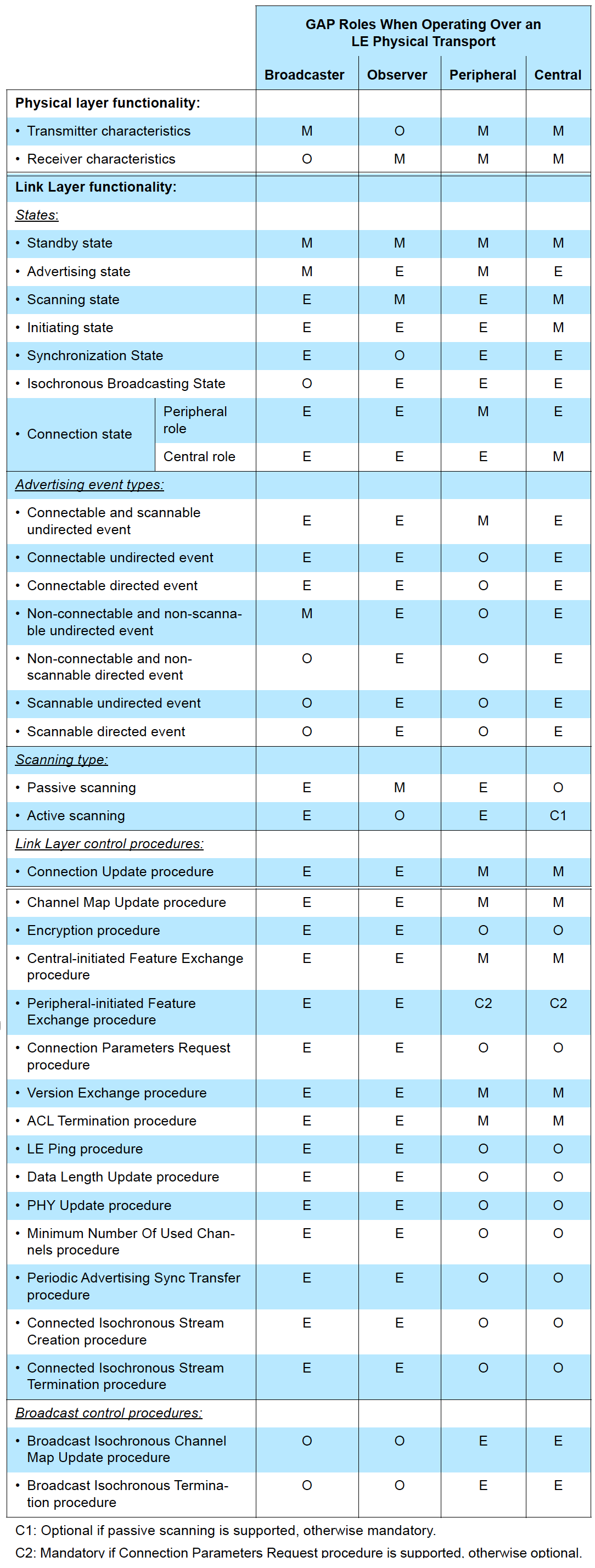
Figure 17: GAP compliance requirements for physical layer and Link Layer functionalities for each GAP role when operating over an LE physical transport
9. Attribute Protocol (ATT)
为了方便物联网设备进行信息采集,BLE 抽象出一个协议:Attribute protocol(ATT),该协议将这些“信息”以“Attribute(属性)”的形式抽象出来,并提供一些方法,供远端设备(Remote Device)读取、修改这些属性的值(Attribute Value)。
什么是 attribute 呢?An attribute is a value that has the following three properties associated with it:
- attribute type, defined by a UUID
- attribute handle
- a set of permissions that are defined by each higher layer specification that utilizes the attribute; these permissions cannot be accessed using the Attribute protocol
可以把 attribute 简单理解为 key-value 数据,key 是 UUID(即 attribute type),而 value 就是 attribute 的 value。
关于 Permissions,有下面 4 类:
- Access Permissions. 可选值为 Readable/Writeable/Readable and writable;
- Encryption Permissions. 可选值为 Encryption Required/No encryption Required;
- Authentication Permissions. 可选值为 Authentication Required/No Authentication Required;
- Authorization Permissions. 可选值为 Authorization Required/No Authorization Required。
10. Generic Attribute Profile (GATT)
GATT uses the Attribute Protocol as its transport protocol to exchange data between devices. This data is organized hierarchically in sections called services, which group conceptually related pieces of user data called characteristics.
也就是说:GATT 在 ATT 之上再抽象出了 services 和 characteristics 概念,以更好地为上层应用服务。
10.1. Roles (Server/Client)
GATT 定义了 2 种 Roles:
- Client. It sends requests to a server and receives responses (and server-initiated updates) from it. The GATT client does not know anything in advance about the server’s attributes, so it must first inquire about the presence and nature of those attributes by performing service discovery. After completing service discovery, it can then start reading and writing attributes found in the server, as well as receiving server-initiated updates.
- Server. It receives requests from a client and sends responses back. It also sends server-initiated updates when configured to do so, and it is the role responsible for storing and making the user data available to the client, organized in attributes.
总结:提供数据的设备称为 GATT Server,访问 GATT Server 而获得数据的设备称为 GATT Client。
所有通过 GATT 传输的数据必须映射成一系列的 Characteristics。 一个 Service 包含一个或多个 Characteristics,每个 Characteristic 可以看作是一个键值对,键是为 Characteristic 所指定的 UUID,值是 Characteristic 本身的 Value。 比如,某传感器中,可以定义温度为一个 Characteristic,而湿度为另一个 Characteristic。 一个 Characteristic 可以包含 0 个或多个 Descriptor,每个 Descriptor 都是对该 Characteristic 的 Value 的描述说明,比如 Value 的单位,描述等等。Descriptor 中存储数据的解析由工程师决定,并无规范,双发按照约定进行开发。
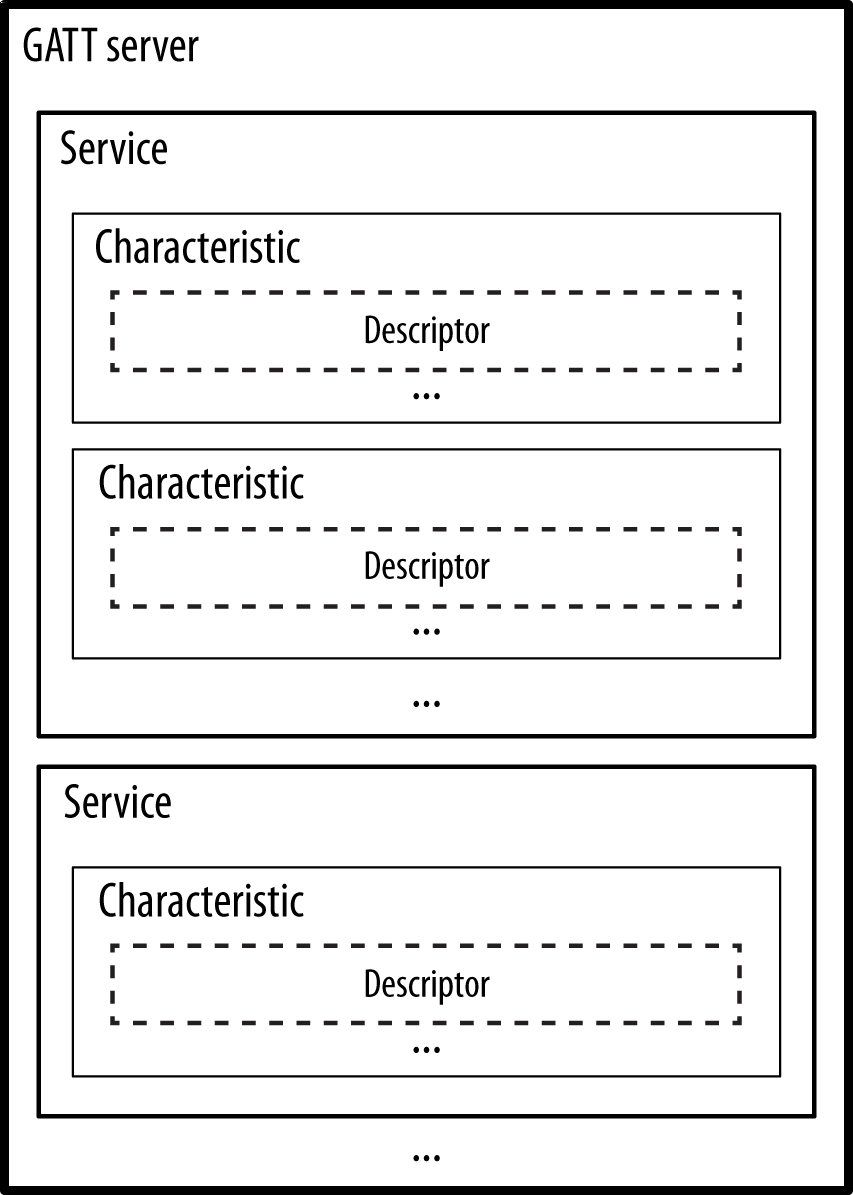
Figure 18: GATT server
10.2. Service 和 Characteristic 的 UUID
有一些 UUID 是预先分配好的,如 0x1805 表示 GATT Service:Current Time,0x2A19 表示 GATT Characteristic:Battery Level。
其它预先分配好的 UUID 可参考:
https://btprodspecificationrefs.blob.core.windows.net/assigned-values/16-bit%20UUID%20Numbers%20Document.pdf
https://www.bluetooth.com/specifications/assigned-numbers/
10.3. Client/Server 和 Central/Peripheral 无必然联系
Client/Server 是 GATT 中定义的 Roles;而 Central/Peripheral 是 GAP 中定义的 Roles;它们之前没有必然关系。也就是说 Central 可以是 GATT Server 或 GATT Client;而 Peripheral 也可以是 GATT Server 或 GATT Client;而且一个设备可以同时是 GATT Server 和 GATT Client。 如图 19 所示(改编自:https://embedded.fm/blog/ble-roles )。
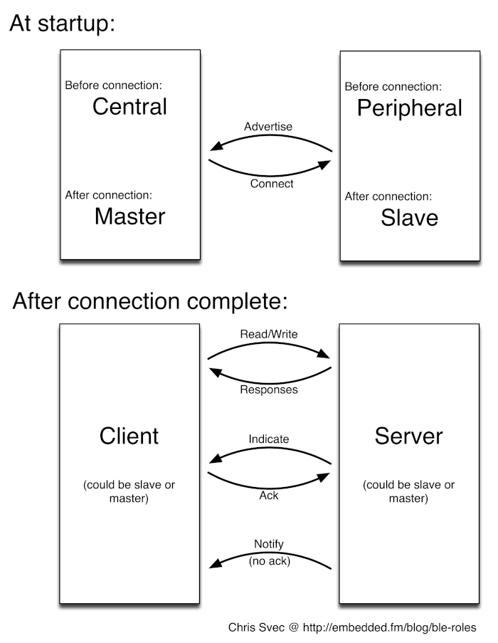
Figure 19: Client/Server VS. Central/Peripheral
不过,最常见的情况还是 Peripheral 作为 GATT Server,而 Central 作为 GATT Client,如图 20 所示(摘自:https://developer.apple.com/library/archive/documentation/NetworkingInternetWeb/Conceptual/CoreBluetooth_concepts/CoreBluetoothOverview/CoreBluetoothOverview.html )。
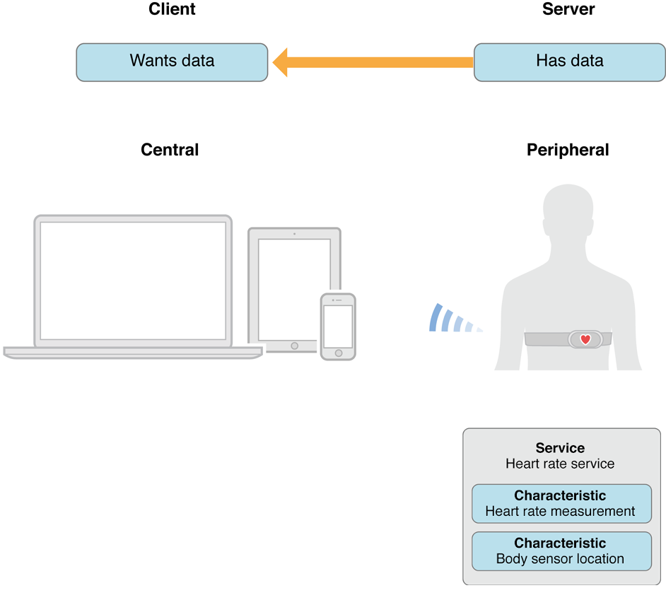
Figure 20: Peripheral 往往作为 GATT Server,而 Central 往往作为 GATT Client
11. Android, iOS
12. Tips
12.1. 20 bytes 限制
在 Bluetooth 4.0 中,对 characteristics 进入写入操作时,最多 20 字节,这个限制的由来参见图 21 。
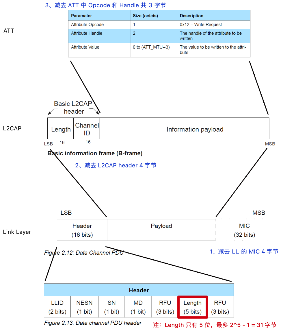
Figure 21: 20 bytes 限制的由来
参考:
https://stackoverflow.com/questions/38913743/maximum-packet-length-for-bluetooth-le
https://punchthrough.com/maximizing-ble-throughput-part-2-use-larger-att-mtu-2/
12.2. RSSI (Received Signal Strength Indication)
RSSI (Received Signal Strength Indication) 这个值越小说明信号越差,反之这个值越大表示信号越好。单位为“分贝毫瓦”,记为 dBm。对于 BLE,它往往为负值,例如,大于 -50 dBm 时表明 BLE 设备之间信号很好;小于 -90 dBm 时,表示 BLE 设备信号很差,几乎无法连接上。
下面是 dBm 和信号强弱的大概关系:
-60 dBm ~ 0 dBm        # BLE 信号很好
-70 dBm ~ -60 dBm      # BLE信号一般
-80 dBm ~ -70 dBm      # BLE 信号差
<-80 dBm               # BLE 信号很差
12.2.1. 由 RSSI 值估计设备之间的距离
由 RSSI 值估计设备之间的距离可采用下面公式:
d = 10^((abs(RSSI) - A) / (10 * n))

其中:
d - 计算所得距离
RSSI - 接收信号强度(往往为负值)
A - 发射端和接收端相隔 1 米时的信号强度
n - 环境衰减因子
由于所处环境不同,每台发射源(蓝牙设备)对应参数值都不一样。按道理,公式里的每项参数都应该做实验(校准)获得。当你不知道周围蓝牙设备准确位置时,可以给 A 和 n 赋经验值:
A = 59
n = 2.0
这样,可以得到下面代码:
- (float)calcDistByRSSI:(int)rssi
{
    int iRssi = abs(rssi);
    float power = (iRssi-59)/(10*2.0);
    return pow(10, power);
}
12.3. MacOS, iOS 下调试蓝牙
苹果公司提供了工具 PacketLogger,可以方便调试蓝牙,其使用可参考:https://www.bluetooth.com/blog/a-new-way-to-debug-iosbluetooth-applications/
13. 参考
- Getting Started with Bluetooth Low Energy
- Bluetooth Core Spec V5.3