IBM IMS Overview
Table of Contents
1. IMS and the Apollo program
On May 25, 1961, United States President John F. Kennedy challenged American industry to send an American man to the moon and return him safely to earth, thus launching the Apollo program. North American Aviation, in partnership with IBM®, fulfilled the requirement for an automated system to manage large bills of material for the construction of the spacecraft in 1965. In 1966, the IBM and North American Aviation teams were joined by three members from Caterpillar Tractor. Together, they designed and developed a system that was called Information Control System and Data Language/Interface (ICS/DL/I).
The IBM team completed and shipped the first release of ICS in Los Angeles in 1967, and in April 1968, ICS was installed. The first “READY” message was displayed on an IBM 2740 typewriter terminal at the Rockwell Space Division at NASA in Downey, California, on August 14, 1968. Less than a year later, on July 20, 1969, Apollo 11 landed on the moon's surface. ICS was subsequently relaunched as Information Management System/360 (IMS/360) and made available to the IT world.
2. Overview of the IMS product
IMS™ consists of three components: IMS Database Manager (IMS DB), IMS Transaction Manager (IMS TM), and a set of system services that provide common services to IMS DB and IMS TM.
Often referred to collectively as IMS DB/DC (DC stems from the original name for the IMS Transaction Manager: Data Communications), these components comprise a complete online transaction and database processing environment that provides continuous availability and data integrity. IMS delivers accurate, consistent, timely, and critical information to application programs, which in turn deliver the information to many end users and programs.
IMS has been developed to provide an environment for applications that require very high levels of performance, throughput, and availability. IMS runs on z/OS® and on zSeries® hardware, and uses many of the facilities offered by the operating system and hardware.
IMS TM and IMS DB can be ordered separately if both components are not required. The appropriate system services are provided for the components that are ordered. When IMS DB is ordered by itself, it is called DB Control (DBCTL). When IMS TM is ordered by itself, it is called DC Control (DCCTL).
2.1. IMS environments
The IMS™ control region is the core of an IMS subsystem, running in one z/OS® address space.
IMS™ provides address spaces for the execution of system and application programs that use IMS services: dependent regions. Dependent regions are started by the submission of JCL to the operating system, or they can run as started tasks.
Figure 1: Structure of a sample IMS DB/DC environment
2.1.1. MPP region
Message processing regions (MPRs) run applications that process messages that IMS Transaction Manager receives as input (for example, from terminals or online programs). The programs that process messages in MPRs are known as message processing programs (MPPs).
2.1.2. BMP region
Batch message processing (BMP) region is not usually started by the IMS control region, but is started by submitting a batch job (for example, by a user from TSO or by a job scheduler). The batch job then connects to an IMS control region that is defined in the execution parameters.
Two types of applications can run in BMP regions:
- Message-driven BMP applications (also called transaction-oriented BMP applications), which read and process messages from the IMS message queue.
- Non-message-driven BMP applications (batch-oriented), which do not process IMS input messages. They can insert IMS output messages.
BMP regions can be used for jobs that, in the past, were run as batch update programs. The advantage of converting batch jobs to run in BMP regions is that the batch jobs can now run along with a transaction environment, and these BMP applications can be run concurrently instead of sequentially. Because these programs are updating online databases and holding locks, it is important that they take checkpoints on a regular basis.
3. IMS DB
IMS uses a hierarchical model as the basic method of storing data. Unlike the relational model used by DB2, which was the result of theoretical work, the hierarchical model was arrived at as a pragmatic way of storing and retrieving data quickly while using as few computer resources as possible.
3.1. How data is stored in a database
The data in a database is grouped into a series of database records. Each database record is composed of smaller groups of data called segments. A segment is the smallest piece of data IMS can store.
The figure 2 shows a record in a school database. Each of the boxes is a segment in the database record.
Figure 2: Segment types in the school database record
Only one root segment exists within a database record. All other segments in the database record are called dependent segments.
3.1.1. Segment type and occurrence
The terms segment type and segment occurrence distinguish between a type of segment in the database and a specific segment instance.
Figure 2 shows the segment types for the database. Figure 3 shows the actual database record with the segment occurrences.
Figure 3: Segment occurrences in the school database record
3.1.2. Field
A segment consists of related fields to collect the information of an entity. For example, Roll No, Name, Course, and Mobile No are fields in following Student segment.
| Student | |||
| Roll No | Name | Course | Mobile No |
3.2. The hierarchy in a database record
When a database record is stored in the database, the hierarchical arrangement of segments in the database record is the order in which segments are stored.
The sequence in which segments are stored is loosely called "top to bottom, left to right."
The figure 4 shows sequencing of segment types for the school database shown in figure 2.
Figure 4: Hierarchical sequence of segment types for a school database
The figure 5 shows the segment occurrences for the school database record as shown in 3. Because there are multiple occurrences of segment types, segments are read "front to back" in addition to "top to bottom, left to right."
You can refer to sequencing in the hierarchy as "top to bottom, front to back, left to right", but "front to back" only occurs at the bottom of the hierarchy.
Figure 5: Hierarchical sequence of segment occurrences for school database
3.3. Hierarchical model and its ralational representation
IMS uses the term database slightly differently to its use in other DBMSs. In IMS, a database is commonly used to describe the implementation of one hierarchy, so that an application would normally access a large number of IMS databases.
A database segment definition defines the fields for a set of segment instances similar to the way a relational table defines columns for a set of rows in a table. In this regard, segments relate to tables, and fields in a segment relate to columns in a table, as illustrated by comparing figure 6 to figure 7. Similarly, an instance of a segment in a database corresponds to a row (or tuple) in a table.
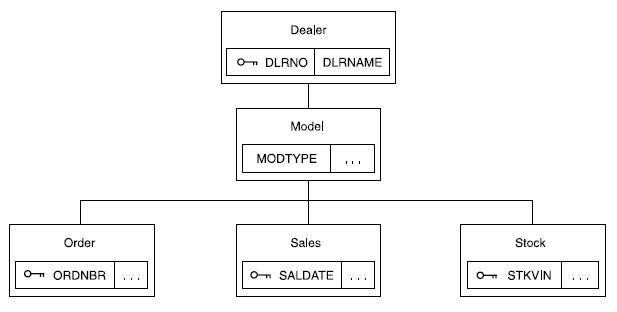
Figure 6: Example of a Hierarchical Dealership Database
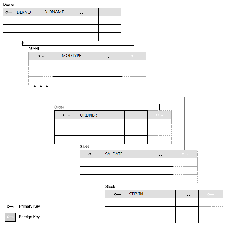
Figure 7: Relational Representation of the Dealership Database
| Hierarchical database elements in IMS | Equivalent relational database elements |
|---|---|
| Segment name | Table name |
| Segment instance | Table row |
| Segment field name | Column name |
| Segment unique key | Table primary key |
| Foreign key field | Table foreign key |
3.4. Types of IMS databases
You need to know that each IMS database has its own access method, because IMS runs under control of the z/OS® operating system. The operating system does not know what a segment is because it processes logical records, not segments.
| Type of IMS database | Full name of database type | IMS or operating system access methods that can be used |
|---|---|---|
| DEDB | Data Entry Database | Media Manager |
| GSAM | Generalized Sequential Access Method | QSAM/BSAM or VSAM |
| HDAM | Hierarchical Direct Access Method | VSAM or OSAM |
| HIDAM | Hierarchical Indexed Direct Access Method | VSAM or OSAM |
| HISAM | Hierarchical Indexed Sequential Access Method | VSAM |
| HSAM | Hierarchical Sequential Access Method | BSAM or QSAM |
| MSDB | Main Storage Database | N/A |
| PHDAM | Partitioned Hierarchical Direct Access Method | VSAM or OSAM |
| PHIDAM | Partitioned Hierarchical Indexed Direct Access Method | VSAM or OSAM |
| PSINDEX | Partitioned Secondary Index | VSAM |
| SHSAM | Simple Hierarchical Sequential Access Method | BSAM or QSAM |
| SHISAM | Simple Hierarchical Indexed Sequential Access Method | VSAM |
Reference:
http://www-01.ibm.com/support/knowledgecenter/SSEPH2_13.1.0/com.ibm.ims13.doc.dag/ims_dbtypes.htm?lang=en
http://www-01.ibm.com/support/knowledgecenter/api/content/nl/en-us/SSEPH2_13.1.0/com.ibm.ims13.doc.dag/ims_dbtype_summary.htm
4. IMS DB - Control Blocks
IMS Control Blocks define the structure of the IMS database and a program's access to them. DL/I uses the following three types of Control Blocks:
- Database Descriptor (DBD)
- Program Specification Block (PSB)
- Access Control Block (ACB)
Reference:
http://www.tutorialspoint.com/ims_db/ims_db_control_blocks.htm
4.1. Database Descriptor (DBD)
The fundamentals of DBD are as given below:
- DBD describes the complete physical structure of the database once all the segments have been defined.
- While installing a DL/I database, one DBD must be created as it is required to access the IMS database.
- The Database Administrator creates a DBD by coding DBDGEN control statements (In relational databases, you create your tables using SQL statements).
4.2. Program Specification Block (PSB)
The fundamentals of PSB are as given below:
- A database has a single physical structure defined by a DBD but the application programs that process it can have different views of the database. These views are called application data structure and are defined in the PSB.
- No program can use more than one PSB in a single execution.
- PSB consists of one or more control blocks called Program Communication Blocks (PCBs). The PSB contains one PCB for each DL/I database the application program will access.
- PSBGEN must be performed to create a PSB for the program.
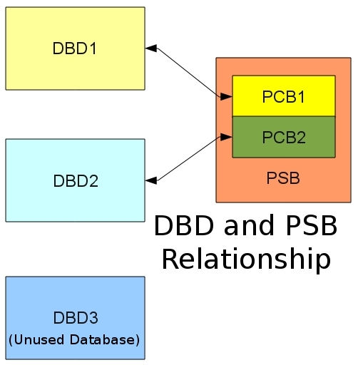
Figure 8: IMS DBD and PSB relationship
Reference:
http://www.conceptsolutionsbc.com/mvs-articles/37-ibm-mainframe/202-what-is-an-ims-database
4.3. Access Control Block (ACB)
When an IMS program executes, IMS has to merge the information in the DBD and PSB. The merged information is called an Application Control Block (ACB). For online applications, the merging of DBD and PSB information needs to be done quickly. This is why there is a need to perform an ACB gen. For Batch processing, there is no need to do an ACB gen since there is no need for fast response time.
Listed below are the points to note about access control blocks:
- Access Control Blocks for an application program combines the Database Descriptor and the Program Specification Block into an executable form.
- ACBGEN is known as Access Control Blocks Generator. It is used to generate ACBs.
- For online programs, we need to pre-build ACBs. Hence the ACBGEN utility is executed before executing the application program.
- For batch programs, ACBs can be generated at execution time too.
5. DL/I
Data Language/I (DL/I) is the IMS™ data manipulation language, which is a common high-level interface between a user application and IMS.
DL/I calls are invoked from application programs written in languages such as PL/I, COBOL, Pascal, C, and Ada.
IMS™ offers several interfaces for DL/I calls:
- A language-independent interface for any programs that are Language Environment® conforming (CEETDLI)
- Language-specific interfaces for all supported languages (xxxTDLI), such as ASMTDLI (Assembly To DL/I), CTDLI (C To DL/I), CBLTDLI(COBOL To DL/I).
- A non-language-specific interface for all supported languages (AIBTDLI)
Figure 9: IMS DL/I overview
References:
http://www.tutorialspoint.com/ims_db/ims_db_overview.htm
http://www-01.ibm.com/support/knowledgecenter/SSEPH2_13.1.0/com.ibm.ims13.doc.dag/ims_dli.htm?lang=en
5.1. DL/I calls inside COBOL
Call statement is used to request for DL/I services such as executing certain operations on the IMS database.
Here is the syntax of the call statement:
CALL 'CBLTDLI' USING [parmcount ,]
                     DLI Function Code
                     , PCB Mask
                     , Segment I/O Area
                     [, Segment Search Arguments].
| Parameter | Description |
|---|---|
| parmcount | Number of parameters in the parameter list that follows parmcount |
| DLI Function Code | Identifies the DL/I function to be performed. This argument is the name of the four character fields that describe the I/O operation. |
| PCB Mask | Program Communication Block (PCB), defined inside the Linkage Section |
| Segment I/O Area | Name of an input/output work area. This is an area of the application program into which the DL/I puts a requested segment. |
| Segment Search Arguments (SSA) | It is used to search data segments inside the IMS database. |
5.1.1. Example of DL/I
The following code example shows how to write an IMS™ program to access the IMS database in COBOL.
       Identification Division.
       Program-ID. BATCOBOL.
       Environment Division.
       Data Division.
       Working-Storage Section.
         01 Func-Codes.
            05 Func-GU          Picture XXXX Value 'GU  '.
      *********************************************'Get Unique'
            05 Func-GHU         Picture XXXX Value 'GHU '.
      *********************************************'Get Hold Unique'
            05 Func-GN          Picture XXXX Value 'GN '.
      *********************************************'Get Next'
            05 Func-GHN         Picture XXXX Value 'GHN '.
      *********************************************'Get Hold Next'
            05 Func-GNP         Picture XXXX Value 'GNP '.
      *********************************************'Get Next within Parent'
            05 Func-GHNP        Picture XXXX Value 'GHNP'.
      *********************************************'Get Hold Next within Parent'
            05 Func-REPL        Picture XXXX Value 'REPL'.
      *********************************************'Replace'
            05 Func-ISRT        Picture XXXX Value 'ISRT'.
      *********************************************'Insert'
            05 Func-DLET        Picture XXXX Value 'DLET'.
      *********************************************'Delete'
            05 Func-CHKP         PIC X(4)    VALUE 'CHKP'.
      *********************************************'Checkpoint'
            05 Func-XRST         PIC X(4)    VALUE 'XRST'.
      *********************************************'Restart'
            05 Func-PCB          PIC X(4)    VALUE 'PCB '.
      *********************************************'PCB'
            05 Parmcount        Picture S9(5) Value +4 Comp-5.
         01 Unqual-SSA.
            05 Seg-Name         Picture X(08) Value  '        '.
            05 Filler           Picture X     Value  ' '.
         01 Qual-SSA-Mast.
            05 Seg-Name-M       Picture X(08) Value 'ROOTMast'.
            05 Begin-Paren-M    Picture X     Value '('.
            05 Key-Name-M       Picture X(08) Value 'KeyMast '.
            05 Kel-Oper-M       Picture X(05) Value ' ='.
            05 Key-Value-M      Picture X(06) Value 'VVVVVV'.
            05 End-Paren-M      Picture X     Value ')'.
         01 Qual-SSA-Det.
            05 Seg-Name-D       Picture X(08) Value 'ROOTDET '.
            05 Begin-Paren-D    Picture X     Value '('.
            05 Key-Name-D       Picture X(08) Value 'KEYDET  '.
            05 Rel-Oper-D       Picture X(05) Value ' ='.
            05 Key-Value-D      Picture X(06) Value 'VVVVVV'.
            05 End-Paren-D      Picture X     Value ')'.
         01 Det-Seg-In.
            05 Data1            Picture X.
            05 Data2            Picture X.
        01 Mast-Seg-In.
            05 Data1            Picture X.
            05 Data2            Picture X.
       linkage section.
         01 IO-PCB.
            05 Filler           Picture X(10).
            05 IO-Status-Code   Picture XX.
            05 Filler           Picture X(20).
         01 DB-PCB-Mast.
            05 Mast-Dbd-Name    Picture X(8).
            05 Mast-Seg-Level   Picture XX.
            05 Mast-Status-Code Picture XX.
            05 Mast-Proc-Opt    Picture XXXX.
            05 Filler           Picture S9(5) Comp-5.
            05 Mast-Seg-Name    Picture X(8).
            05 Mast-Len-KFB     Picture S9(5) Comp-5.
            05 Mast-Nu-Senseg   Picture S9(5) Comp-5.
            05 Mast-Key-FB      Picture X(256).
         01 DB-PCB-Detail.
            05 Det-Dbd-Name     Picture X(8).
            05 Det-Seg-Level    Picture XX.
            05 Det-Status-Code  Picture XX.
            05 Det-Proc-Opt     Picture XXXX.
            05 Filler           Picture S9(5) Comp-5.
            05 Det-Seg-Name     Picture X(8).
            05 Det-Len-KFB      Picture S9(5) Comp-5.
            05 Det-Nu-Senseg    Picture S9(5) Comp-5.
            05 Det-Key-FB       Picture X(256).

       Procedure Division using IO-PCB DB-PCB-Mast DB-PCB-Detail.
           Call 'CBLTDLI' using Func-GU DB-PCB-Detail
                 Det-seg-in Qual-SSA-Det.
            .
            .
           Call 'CBLTDLI' using Parmcount Func-ghu DB-PCB-Mast
                 Mast-seg-in Qual-SSA-Mast.
            .
            .
           Call 'CBLTDLI' using Func-GHN DB-PCB-Mast
                 Mast-seg-in.
            .
            .
           Call 'CBLTDLI' using Func-REPL DB-PCB-Mast
                 Mast-seg-in.
            .
            .
           Goback.
In above sample, we can see each PCB are passed to COBOL program as its parameters (see Procedure Division) when it is invoked.