ROS 3D Modeling and Simulation
Table of Contents
1. ROS 机器人 3D 建模
如果手头没有真实的机器人,对机器人进行 3D 建模后进行模拟测试是非常的方便手段。
参考:
Learning ROS for Robotics Programming - Second Edition, Chapter 7 3D Modeling and Simulation
1.1. URDF 简介
Unified Robot Description Format (URDF)是一个 XML 文件,用来描述一个机器人。URDF 文件由一系列 link 元素,以及连接 link 元素的 jont 元素组成。
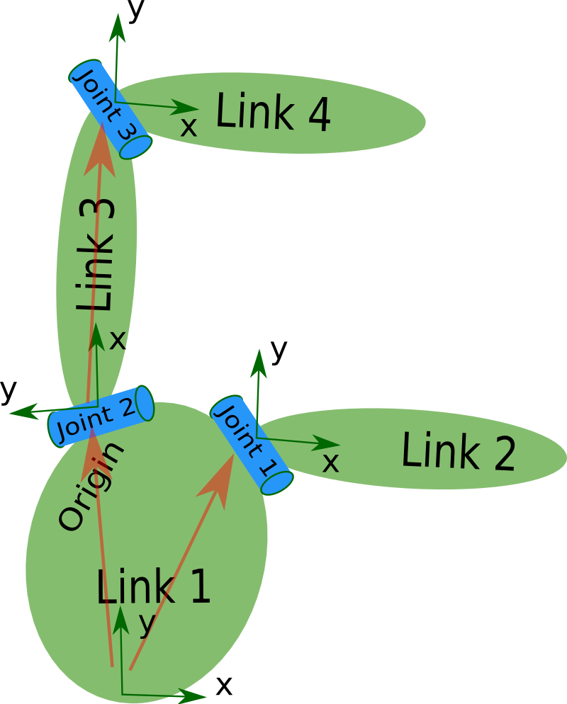
Figure 1: link elements and joint elements
一个机器人的 URDF 文件其结构如下所示:
<robot name="pr2">
  <link> ... </link>
  <link> ... </link>
  <link> ... </link>

  <joint>  ....  </joint>
  <joint>  ....  </joint>
  <joint>  ....  </joint>
</robot>
参考:
http://wiki.ros.org/urdf/XML/model
http://wiki.ros.org/urdf/Tutorials
1.2. 第一个 URDF 实例
下面的 URDF 描述的是一个带有四个轮子的小车。
<?xml version="1.0"?>
<robot name="Robot1">

  <link name="base_link">
    <visual>
      <geometry>
        <box size="0.2 .3 .1"/>
      </geometry>
      <origin rpy="0 0 0" xyz="0 0 0.05"/>
      <material name="white">
        <color rgba="1 1 1 1"/>
      </material>
    </visual>
  </link>

  <link name="wheel_1">
    <visual>
      <geometry>
        <cylinder length="0.05" radius="0.05"/>
      </geometry>
      <origin rpy="0 1.5 0" xyz="0.1 0.1 0"/>
      <material name="black">
        <color rgba="0 0 0 1"/>
      </material>
    </visual>
  </link>

  <link name="wheel_2">
    <visual>
      <geometry>
        <cylinder length="0.05" radius="0.05"/>
      </geometry>
      <origin rpy="0 1.5 0" xyz="-0.1 0.1 0"/>
      <material name="black"/>
    </visual>
  </link>

  <link name="wheel_3">
    <visual>
      <geometry>
        <cylinder length="0.05" radius="0.05"/>
      </geometry>
      <origin rpy="0 1.5 0" xyz="0.1 -0.1 0"/>
      <material name="black"/>
    </visual>
  </link>

  <link name="wheel_4">
    <visual>
      <geometry>
        <cylinder length="0.05" radius="0.05"/>
      </geometry>
      <origin rpy="0 1.5 0" xyz="-0.1 -0.1 0"/>
      <material name="black"/>
    </visual>
  </link>

  <joint name="base_to_wheel1" type="fixed">
    <parent link="base_link"/>
    <child link="wheel_1"/>
    <origin xyz="0 0 0"/>
  </joint>

  <joint name="base_to_wheel2" type="fixed">
    <parent link="base_link"/>
    <child link="wheel_2"/>
    <origin xyz="0 0 0"/>
  </joint>

  <joint name="base_to_wheel3" type="fixed">
    <parent link="base_link"/>
    <child link="wheel_3"/>
    <origin xyz="0 0 0"/>
  </joint>

  <joint name="base_to_wheel4" type="fixed">
    <parent link="base_link"/>
    <child link="wheel_4"/>
    <origin xyz="0 0 0"/>
  </joint>
</robot>
1.2.1. 在 rviz 中查看 URDF 模型
执行下面命令可以在 rviz 中查看前面介绍的 URDF 模型(假设上面 xml 的文件名为 first.urdf):
$ roslaunch urdf_tutorial display.launch model:=first.urdf gui:=True
命令成功执行后,会在 rviz 中显示如图 2 所示模型。
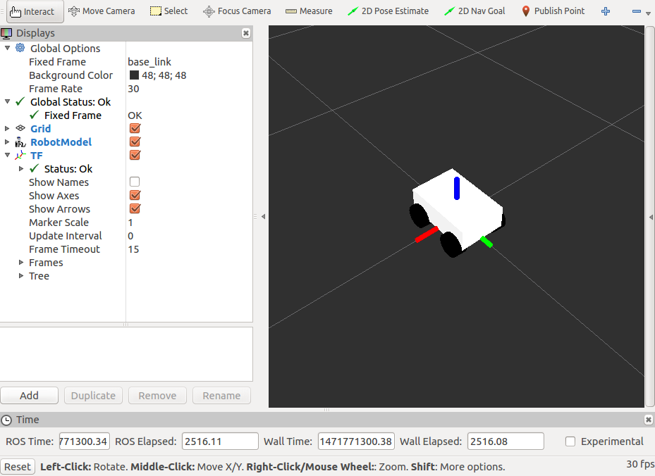
Figure 2: 在 rviz 中查看 URDF 模型
1.3. 增加物理和碰撞属性
要对机器人在软件中进行模拟,必须先对 URDF 模拟中的所有 link 元素增加物理和碰撞属性(即 URDF 中的 collision 标记和 inertial 标记)。如果没有这些属性,则无法在 Gazebo 等软件中模拟机器人。
下面是为 link 元素增加物理和碰撞属性(即 collision 标记和 inertial 标记)的例子:
<link name="wheel_1">
  ...
  <collision>
    <geometry>
      <cylinder length="0.05" radius="0.05"/>
    </geometry>
  </collision>
  <inertial>
    <mass value="10"/>
    <inertia ixx="1.0" ixy="0.0" ixz="0.0" iyy="1.0" iyz="0.0" izz="1.0"/>
  </inertial>
</link>
1.4. 用 Xacro 简化 URDF 编写
Xacro (XML Macros) is an XML macro language. With xacro, you can construct shorter and more readable XML files by using macros that expand to larger XML expressions.
用 Xacro 可以简化 URDF 的编写,Xacro 的完整文档可查阅:http://wiki.ros.org/xacro ,这里仅介绍一些基本的用法。
1.4.1. 宏(xacro:macro)
用 xacro:macro 可以定义一个宏,可以用 xacro:name_of_macro 使用一个已经定义的宏。如:
<xacro:macro name="pr2_arm" params="suffix parent reflect">
  <pr2_upperarm suffix="${suffix}" reflect="${reflect}" parent="${parent}" />
  <pr2_forearm suffix="${suffix}" reflect="${reflect}" parent="elbow_flex_${suffix}" />
</xacro:macro>

<xacro:pr2_arm suffix="left" reflect="1" parent="torso" />
<xacro:pr2_arm suffix="right" reflect="-1" parent="torso" />
会展开为:
<pr2_upperarm suffix="left" reflect="1" parent="torso" />
<pr2_forearm suffix="left" reflect="1" parent="elbow_flex_left" />
<pr2_upperarm suffix="right" reflect="-1" parent="torso" />
<pr2_forearm suffix="right" reflect="-1" parent="elbow_flex_right" />
1.4.2. 属性和属性块(xacro:property)
用 xacro:property 可以定义一个 property,用 ${name_of_property} 可以使用一个已经定义的 property。如:
<xacro:property name="the_radius" value="2.1" />
<xacro:property name="the_length" value="4.5" />

<geometry type="cylinder" radius="${the_radius}" length="${the_length}" />
会展开为:
<geometry type="cylinder" radius="2.1" length="4.5" />
此外,用 xacro:property 还可以定义一个 property block,用 xacro:insert_block 可以使用一个已经定义的 property block。如:
<xacro:property name="front_left_origin">
  <origin xyz="0.3 0 0" rpy="0 0 0" />
</xacro:property>

<pr2_wheel name="front_left_wheel">
  <xacro:insert_block name="front_left_origin" />
</pr2_wheel>
会展开为:
<pr2_wheel name="front_left_wheel">
  <origin xyz="0.3 0 0" rpy="0 0 0" />
</pr2_wheel>
1.4.3. 实例:转换 Xacro 文件为 URDF 文件
用命令 rosrun xacro xacro.py filename.xacro >filename.urdf 可以把 Xacro 文件转换为对应的 URDF 文件。
假设有下面 URDF 文件,文件中有很多相似的代码,如果要修改某个设置,可能需要在很多不同的位置进行相应的修改,这不是很方便。如果改写为 Xacro 文件,则不仅代码量更少,而且修改设置也更加方便。
<?xml version="1.0" ?>
<robot name="Robot1">
  <link name="base_link">
    <visual>
      <geometry>
        <box size="0.2 .3 .1"/>
      </geometry>
      <origin rpy="0 0 0" xyz="0 0 0.05"/>
      <material name="white">
        <color rgba="1 1 1 1"/>
      </material>
    </visual>
    <collision>
      <geometry>
        <box size="0.2 .3 0.1"/>
      </geometry>
    </collision>
    <inertial>
      <mass value="10"/>
      <inertia ixx="1.0" ixy="0.0" ixz="0.0" iyy="1.0" iyz="0.0" izz="1.0"/>
    </inertial>
  </link>
  <link name="wheel_1">
    <visual>
      <geometry>
        <cylinder length="0.05" radius="0.05"/>
      </geometry>
      <origin rpy="0 1.5 0" xyz="0.1 0.1 0"/>
      <material name="black">
        <color rgba="0 0 0 1"/>
      </material>
    </visual>
    <collision>
      <geometry>
        <cylinder length="0.05" radius="0.05"/>
      </geometry>
    </collision>
    <inertial>
      <mass value="10"/>
      <inertia ixx="1.0" ixy="0.0" ixz="0.0" iyy="1.0" iyz="0.0" izz="1.0"/>
    </inertial>
  </link>
  <link name="wheel_2">
    <visual>
      <geometry>
        <cylinder length="0.05" radius="0.05"/>
      </geometry>
      <origin rpy="0 1.5 0" xyz="-0.1 0.1 0"/>
      <material name="black"/>
    </visual>
    <collision>
      <geometry>
        <cylinder length="0.05" radius="0.05"/>
      </geometry>
    </collision>
    <inertial>
      <mass value="10"/>
      <inertia ixx="1.0" ixy="0.0" ixz="0.0" iyy="1.0" iyz="0.0" izz="1.0"/>
    </inertial>
  </link>
  <link name="wheel_3">
    <visual>
      <geometry>
        <cylinder length="0.05" radius="0.05"/>
      </geometry>
      <origin rpy="0 1.5 0" xyz="0.1 -0.1 0"/>
      <material name="black"/>
    </visual>
    <collision>
      <geometry>
        <cylinder length="0.05" radius="0.05"/>
      </geometry>
    </collision>
    <inertial>
      <mass value="10"/>
      <inertia ixx="1.0" ixy="0.0" ixz="0.0" iyy="1.0" iyz="0.0" izz="1.0"/>
    </inertial>
  </link>
  <link name="wheel_4">
    <visual>
      <geometry>
        <cylinder length="0.05" radius="0.05"/>
      </geometry>
      <origin rpy="0 1.5 0" xyz="-0.1 -0.1 0"/>
      <material name="black"/>
    </visual>
    <collision>
      <geometry>
        <cylinder length="0.05" radius="0.05"/>
      </geometry>
    </collision>
    <inertial>
      <mass value="10"/>
      <inertia ixx="1.0" ixy="0.0" ixz="0.0" iyy="1.0" iyz="0.0" izz="1.0"/>
    </inertial>
  </link>
  <joint name="base_to_wheel1" type="fixed">
    <parent link="base_link"/>
    <child link="wheel_1"/>
    <origin xyz="0 0 0"/>
  </joint>
  <joint name="base_to_wheel2" type="fixed">
    <parent link="base_link"/>
    <child link="wheel_2"/>
    <origin xyz="0 0 0"/>
  </joint>
  <joint name="base_to_wheel3" type="fixed">
    <parent link="base_link"/>
    <child link="wheel_3"/>
    <origin xyz="0 0 0"/>
  </joint>
  <joint name="base_to_wheel4" type="fixed">
    <parent link="base_link"/>
    <child link="wheel_4"/>
    <origin xyz="0 0 0"/>
  </joint>
</robot>
编写如下所示的 Xacro 文件可以展开为上面的 URDF 文件。
<?xml version="1.0"?>
<robot xmlns:xacro="http://www.ros.org/wiki/xacro" name="Robot1">
  <xacro:property name="length_wheel" value="0.05" />
  <xacro:property name="radius_wheel" value="0.05" />
  <xacro:macro name="default_inertial" params="mass">
    <inertial>
      <mass value="${mass}" />
      <inertia ixx="1.0" ixy="0.0" ixz="0.0" iyy="1.0" iyz="0.0" izz="1.0" />
    </inertial>
  </xacro:macro>

  <link name="base_link">
    <visual>
      <geometry>
        <box size="0.2 .3 .1"/>
      </geometry>
      <origin rpy="0 0 0" xyz="0 0 0.05"/>
      <material name="white">
        <color rgba="1 1 1 1"/>
      </material>
    </visual>
    <collision>
      <geometry>
        <box size="0.2 .3 0.1"/>
      </geometry>
    </collision>
    <xacro:default_inertial mass="10"/>
  </link>
  <link name="wheel_1">
    <visual>
      <geometry>
        <cylinder length="${length_wheel}" radius="${radius_wheel}"/>
      </geometry>
      <origin rpy="0 1.5 0" xyz="0.1 0.1 0"/>
      <material name="black">
        <color rgba="0 0 0 1"/>
      </material>
    </visual>
    <collision>
      <geometry>
        <cylinder length="${length_wheel}" radius="${radius_wheel}"/>
      </geometry>
    </collision>
    <xacro:default_inertial mass="10"/>
  </link>
  <link name="wheel_2">
    <visual>
      <geometry>
        <cylinder length="${length_wheel}" radius="${radius_wheel}"/>
      </geometry>
      <origin rpy="0 1.5 0" xyz="-0.1 0.1 0"/>
      <material name="black"/>
    </visual>
    <collision>
      <geometry>
        <cylinder length="${length_wheel}" radius="${radius_wheel}"/>
      </geometry>
    </collision>
    <xacro:default_inertial mass="10"/>
  </link>
  <link name="wheel_3">
    <visual>
      <geometry>
        <cylinder length="${length_wheel}" radius="${radius_wheel}"/>
      </geometry>
      <origin rpy="0 1.5 0" xyz="0.1 -0.1 0"/>
      <material name="black"/>
    </visual>
    <collision>
      <geometry>
        <cylinder length="${length_wheel}" radius="${radius_wheel}"/>
      </geometry>
    </collision>
    <xacro:default_inertial mass="10"/>
  </link>
  <link name="wheel_4">
    <visual>
      <geometry>
        <cylinder length="${length_wheel}" radius="${radius_wheel}"/>
      </geometry>
      <origin rpy="0 1.5 0" xyz="-0.1 -0.1 0"/>
      <material name="black"/>
    </visual>
    <collision>
      <geometry>
        <cylinder length="${length_wheel}" radius="${radius_wheel}"/>
      </geometry>
    </collision>
    <xacro:default_inertial mass="10"/>
  </link>

  <joint name="base_to_wheel1" type="fixed">
    <parent link="base_link"/>
    <child link="wheel_1"/>
    <origin xyz="0 0 0"/>
  </joint>
  <joint name="base_to_wheel2" type="fixed">
    <parent link="base_link"/>
    <child link="wheel_2"/>
    <origin xyz="0 0 0"/>
  </joint>
  <joint name="base_to_wheel3" type="fixed">
    <parent link="base_link"/>
    <child link="wheel_3"/>
    <origin xyz="0 0 0"/>
  </joint>
  <joint name="base_to_wheel4" type="fixed">
    <parent link="base_link"/>
    <child link="wheel_4"/>
    <origin xyz="0 0 0"/>
  </joint>
</robot>
假设上面 Xacro 文件名为 robot1.xacro,则可以用下面命令转换为 URDF 文件(名为 robot1_processed.urdf):
$ rosrun xacro xacro.py robot1.xacro >robot1_processed.urdf
2. Simulation in ROS
Gazebo 是机器人模拟工具,它独立于 ROS。
ROS 的机器人描述 URDF 文件可以被 Gazebo 识别(注:Gazebo 有自己的机器人描述格式 SDF)。
要在 ROS 中集成 Gazebo,需要用到 ROS 功能包 gazebo_ros_pkgs ,它是一些功能包(如 gazebo_ros, gazebo_msgs, gazebo_plugins)的集合。
2.1. gazebo_ros_pkgs
gazebo_ros_pkgs 是在 ROS 中集成 Gazebo 时必需安装的包,它所包含的功能包及主要用法如图 3 所示。
Figure 3: An overview of the gazebo_ros_pkgs interface
当完整安装 ROS 时,gazebo_ros_pkgs 已经安装好,可以用下面命令测试是否 ROS 和 Gazebo 的集成已经准备好。
$ roslaunch gazebo_ros empty_world.launch # 会启动gazebo中内置的worlds/empty.world文件
正常启动后,会出现如图 4 所示界面。
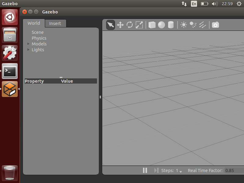
Figure 4: empty world in gazebo_ros
在 gazebo_ros 包中,还内置了其它一些启动文件。如:
$ roslaunch gazebo_ros willowgarage_world.launch     # 会启动gazebo中内置的worlds/willowgarage.world文件
$ roslaunch gazebo_ros shapes_world.launch           # 会启动gazebo中内置的worlds/shapes.world文件
运行上面两个命令,正常启动后,分别可得到如图 5 和图 6 所示界面。
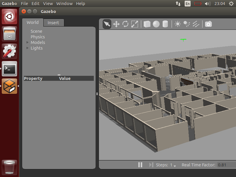
Figure 5: willowgarage_world in ros_gazebo
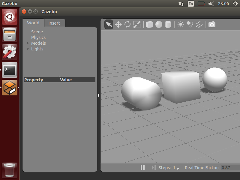
Figure 6: shapes_world in ros_gazebo
2.2. Gazebo 中模拟 URDF 定义的机器人
怎么把 URDF 文件描述的机器人放入到 Gazebo 中模拟呢?有两种方法。
方法一,先用 gazebo_ros 中内置的启动文件启动 Gazebo,然后用“ROS Service Call”把 URDF 定义的机器人生成在 Gazebo 中。
方法二,根据 URDF 文件定义一个 Gazebo 识别的 Model,再把这个 Model 加入到 World 文件中,用 Gazebo 启动 World 文件即可。
这里仅介绍方法一。方法一的操作实例如下:
第一步,执行下面命令启动 Gazebo:
$ roslaunch gazebo_ros empty_world.launch
第二步,用“ROS Service Call”生成 URDF 机器人到 Gazebo 中:
$ rosrun gazebo_ros spawn_model -file robot1_processed.urdf -urdf -x 0 -y 0 -z 1 -model robot1
文件 robot1_processed.urdf 描述的是一个四轮简易机器人,在前文中对它有详细介绍。
spawn_model 是 gazebo_ros 包中的一个 python 脚本,它的作用是“make a service call request to the gazebo_ros ROS node (named simply "gazebo" in the rostopic namespace) to add a custom URDF into Gazebo”,它的详细说明可通过命令 rosrun gazebo_ros spawn_model -h 得到。
一切正常的话,可以在 Gazebo 中看到图 7 所示的机器人。
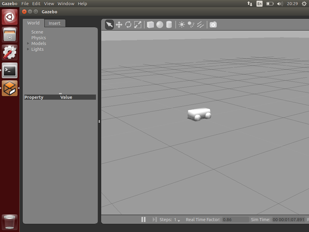
Figure 7: spawn_model 把 robot1_processed.urdf 描述的机器人加载到了 Gazebo 中
参考:http://gazebosim.org/tutorials?tut=ros_roslaunch&cat=connect_ros#UsingroslaunchtoSpawnURDFRobots
2.2.1. 给机器人增加颜色
前面例子中,尽管在 URDF 文件(robot1_processed.urdf)中指定了轮子为黑色,但在 Gazebo 中并没有识别它。要在 Gazebo 中为机器人增加颜色,必须使用 <gazebo>...</gazebo> 标签。
比如,我们想要把机器人的轮子变为黑色,底盘变为橙色,可以在 robot1_processed.urdf 中增加下面的 <gazebo>...<material> ...</material></gazebo> 标签:
<robot>
  ......
  <gazebo reference="base_link">
    <material>Gazebo/Orange</material>
  </gazebo>
  <gazebo reference="wheel_1">
    <material>Gazebo/Black</material>
  </gazebo>
  <gazebo reference="wheel_2">
    <material>Gazebo/Black</material>
  </gazebo>
  <gazebo reference="wheel_3">
    <material>Gazebo/Black</material>
  </gazebo>
  <gazebo reference="wheel_4">
    <material>Gazebo/Black</material>
  </gazebo>
</robot>
重新运行下面两个命令,可得图 8 所示的机器人。
$ roslaunch gazebo_ros empty_world.launch
$ rosrun gazebo_ros spawn_model -file robot1_processed.urdf -urdf -x 0 -y 0 -z 1 -model robot1
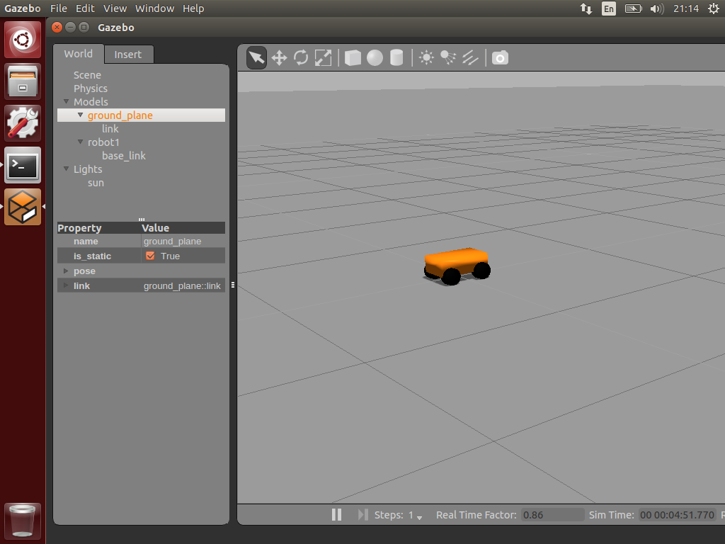
Figure 8: 用<gazebo>...<material> ...</material></gazebo>标签可指定在 Gazebo 中的机器人部件的颜色
参考:http://gazebosim.org/tutorials?tut=ros_urdf&cat=connect_ros
3. 创建用于 Gazebo 模拟的 ROS 包
为了便于操作在 Gazebo 中模拟机器人,一般在 ROS 中创建下面两个包(MYROBOT_description 和 MYROBOT_gazebo,其中 MYROBOT 是占位符,要把它替换为你的机器人名字,且一般用小写):
~/catkin_ws/src
    /MYROBOT_description
        package.xml
        CMakeLists.txt
        /urdf
            MYROBOT.urdf
        /meshes
            mesh1.dae
            mesh2.dae
            ...
        /materials
        /cad
    /MYROBOT_gazebo                       # 这个包保存和 Gazebo 相关的文件
        /launch
            MYROBOT.launch
        /worlds
            MYROBOT.world
        /models
            world_object1.dae
            world_object2.stl
            world_object3.urdf
        /materials
        /plugins
例如在“Learning ROS for Robotics Programming - Second Edition”一书第 7 章,为了在 Gazebo 中模拟机器人 robot1,定义了两个包 robot1_description 和 robot1_gazebo。参考:https://github.com/AaronMR/Learning_ROS_for_Robotics_Programming_2nd_edition/tree/hydro-devel/chapter7_tutorials
参考:http://gazebosim.org/tutorials?tut=ros_roslaunch&cat=connect_ros#CreatingyourownGazeboROSPackage
3.1. 增加传感器和驱动(使用 Gazebo plugins)
一般地,我们把传感器的 3D 模型提前设计好,保存为 COLLADA 格式(常为 dae 后缀,参考:https://en.wikipedia.org/wiki/COLLADA) 或者 stl 格式(参:https://en.wikipedia.org/wiki/STL_(file_format)%EF%BC%89%EF%BC%8C%E5%9C%A8URDF%E4%B8%AD%E5%8F%AF%E4%BB%A5%E7%9B%B4%E6%8E%A5%E5%BC%95%E7%94%A8%E8%BF%99%E4%B8%A4%E7%A7%8D%E6%A0%BC%E5%BC%8F%E7%9A%843D%E6%A8%A1%E5%9E%8B。
假设 Hokuyo 激光测距仪的 3D 模型为 hokuyo.dae ,保存在包 robot1_description 中。在 Mac 10.10 中可以用 Preview 程序打开它(Linux 中可以安装 MeshLab 等软件来查看它),如图 9 所示。
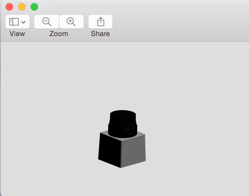
Figure 9: Hokuyo 激光测距仪(hokuyo.dae)
在 URDF 文件可以这样引用包 robot1_description 中的 Hokuyo 激光测距仪:
<?xml version="1.0" encoding="UTF-8"?>
<robot>
......
  <!-- Hokuyo Laser -->
  <link name="hokuyo_link">
    <visual>
      <origin xyz="0 0 0" rpy="0 0 0" />
      <geometry>
        <mesh filename="package://robot1_description/meshes/hokuyo.dae" />
      </geometry>
    </visual>
    <collision>
      <origin xyz="0 0 0" rpy="0 0 0" />
      <geometry>
        <box size="0.1 0.1 0.1" />
      </geometry>
    </collision>
    <inertial>
      <mass value="1e-5" />
      <origin xyz="0 0 0" rpy="0 0 0" />
      <inertia ixx="1e-6" ixy="0" ixz="0" iyy="1e-6" iyz="0" izz="1e-6" />
    </inertial>
  </link>

  <!-- Hokuyo joint -->
  <joint name="hokuyo_joint" type="fixed">
    <origin xyz="0.125 0.05 0.125" rpy="0 0 0"/>
    <parent link="base_link"/>
    <axis xyz="0 1 0" />
    <child link="hokuyo_link"/>
  </joint>
</robot>
把 Hokuyo 激光测距仪集成到前面介绍的四轮简易机器人中,可以得到如图 10 所示机器人。
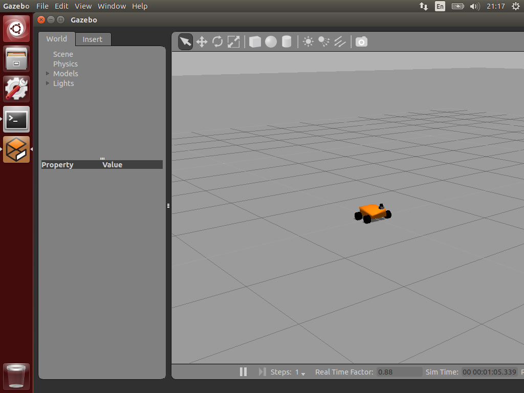
Figure 10: 带有 Hokuyo 激光测距仪的四轮简易机器人
如果要使 Hokuyo 激光测试仪产生“真实”数据,还需要加入类似下面的代码到 URDF 文件中。
  <!-- hokuyo -->
  <gazebo reference="hokuyo_link">
    <sensor type="ray" name="head_hokuyo_sensor">
      <pose>0 0 0 0 0 0</pose>
      <visualize>false</visualize>
      <update_rate>40</update_rate>
      <ray>
        <scan>
          <horizontal>
            <samples>720</samples>
            <resolution>1</resolution>
            <min_angle>-1.570796</min_angle>
            <max_angle>1.570796</max_angle>
          </horizontal>
        </scan>
        <range>
          <min>0.10</min>
          <max>30.0</max>
          <resolution>0.01</resolution>
        </range>
        <noise>
          <type>gaussian</type>
          <!-- Noise parameters based on published spec for Hokuyo laser
               achieving "+-30mm" accuracy at range < 10m.  A mean of 0.0m and
               stddev of 0.01m will put 99.7% of samples within 0.03m of the true
               reading. -->
          <mean>0.0</mean>
          <stddev>0.01</stddev>
        </noise>
      </ray>
      <plugin name="gazebo_ros_head_hokuyo_controller" filename="libgazebo_ros_laser.so">
        <topicName>/robot/laser/scan</topicName>
        <frameName>hokuyo_link</frameName>
      </plugin>
    </sensor>
  </gazebo>
在机器人的模拟过程中,可以通过下面命令看到 Hokuyo 激光测距仪产生的数据。
$ rostopic echo /robot/laser/scan # 这个Topic的名字是在Hokuyo激光测距仪中设置的。
得到的 Laser 数据,其格式如下所示:
header:
  seq: 19
  stamp:
    secs: 32
    nsecs: 568000000
  frame_id: hokuyo_link
angle_min: -1.57079994678
angle_max: 1.57079994678
angle_increment: 0.00436940183863
time_increment: 0.0
scan_time: 0.0
range_min: 0.10000000149
range_max: 30.0
ranges: [6.075214385986328, 6.072081565856934, ...]
intensities: [1.2611686178923354e-44, 1.2611686178923354e-44, ...]
关于 Laser 数据格式的说明,可参考:Introduction to Working With Laser Scanner Data
用 rviz 可以直观地显示 Laser 数据,可参考:Learning ROS for Robotics Programming - Second Edition, Chapter 4 Using Sensors and Actuators with ROS
其它参考资料:Tutorial: Using Gazebo plugins with ROS
3.1.1. 让机器人动起来
对于前面介绍的四轮简易机器人,我们可以增加一个 Skid Steering Drive(滑轨导向驱动),使它可以动起来。
<gazebo>
  <plugin name="skid_steer_drive_controller" filename="libgazebo_ros_skid_steer_drive.so">
    <updateRate>100.0</updateRate>
    <robotNamespace>/</robotNamespace>
    <leftFrontJoint>base_to_wheel1</leftFrontJoint>
    <rightFrontJoint>base_to_wheel3</rightFrontJoint>
    <leftRearJoint>base_to_wheel2</leftRearJoint>
    <rightRearJoint>base_to_wheel4</rightRearJoint>
    <wheelSeparation>4</wheelSeparation>
    <wheelDiameter>0.1</wheelDiameter>
    <robotBaseFrame>base_link</robotBaseFrame>
    <torque>1</torque>
    <topicName>cmd_vel</topicName>
    <broadcastTF>0</broadcastTF>
  </plugin>
</gazebo>
In this case, when you publish a sensor_msgs/Twist topic call /cmd_vel, the robot will move.
完整的例子可参考:Learning ROS for Robotics Programming - Second Edition, Chapter 7 3D Modeling and Simulation